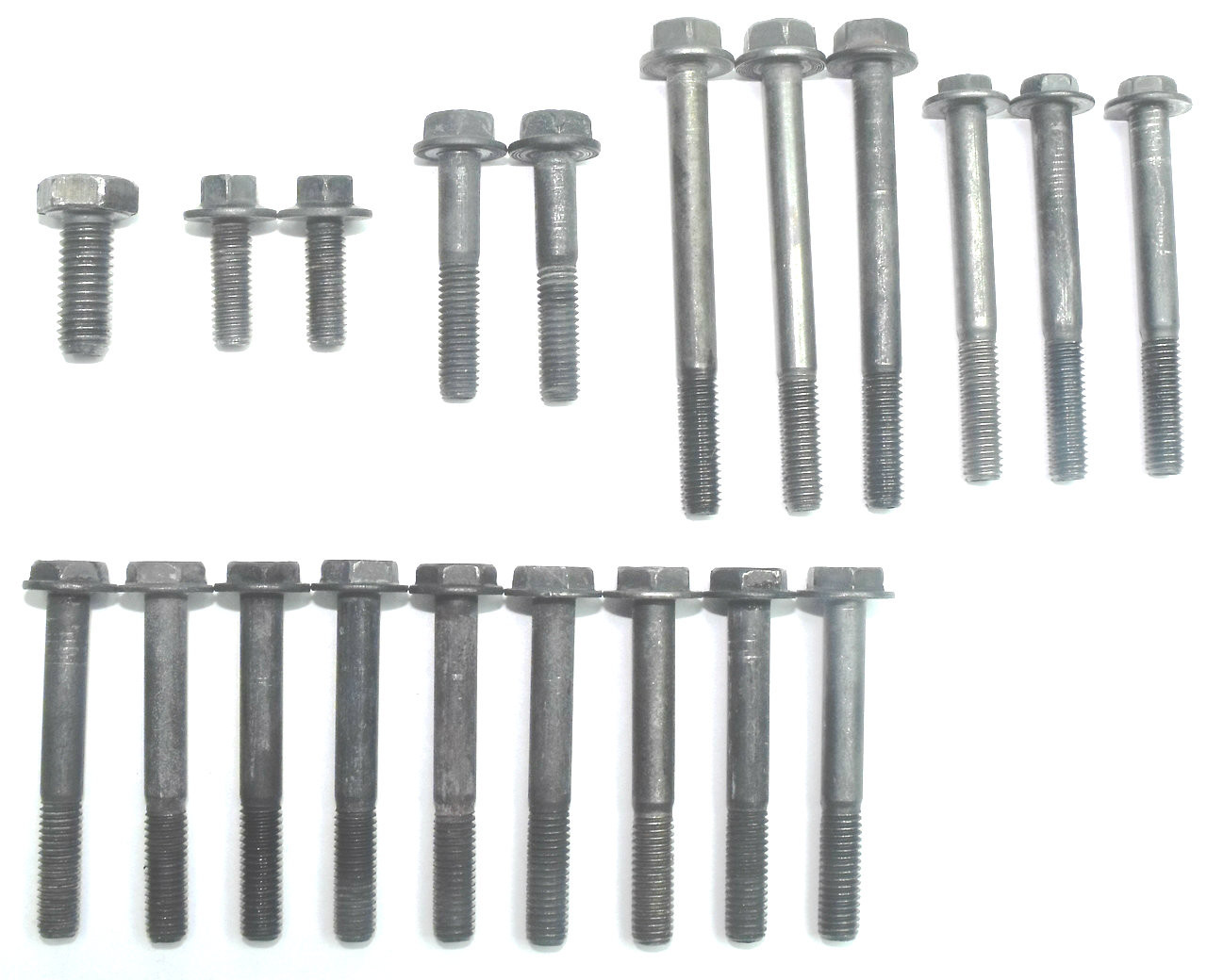
4L60E Master Valve Body Bolt Set (20 Total Bolts)
Fits '94-later 4T60-E. Does not fit 4T65-E Geartronic® or Tapshift® units. Helps cure: Erratic shifts. 2-3 Shuttle. No 3rd. Temperature-sensitive shifts. No 4th. 2nd Gear starts.

30+ 4l60e valve body bolt diagram DarinNeevah
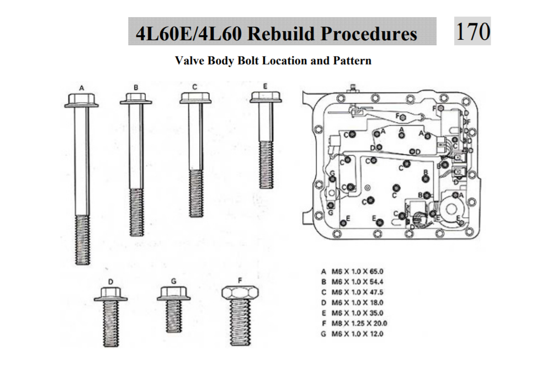
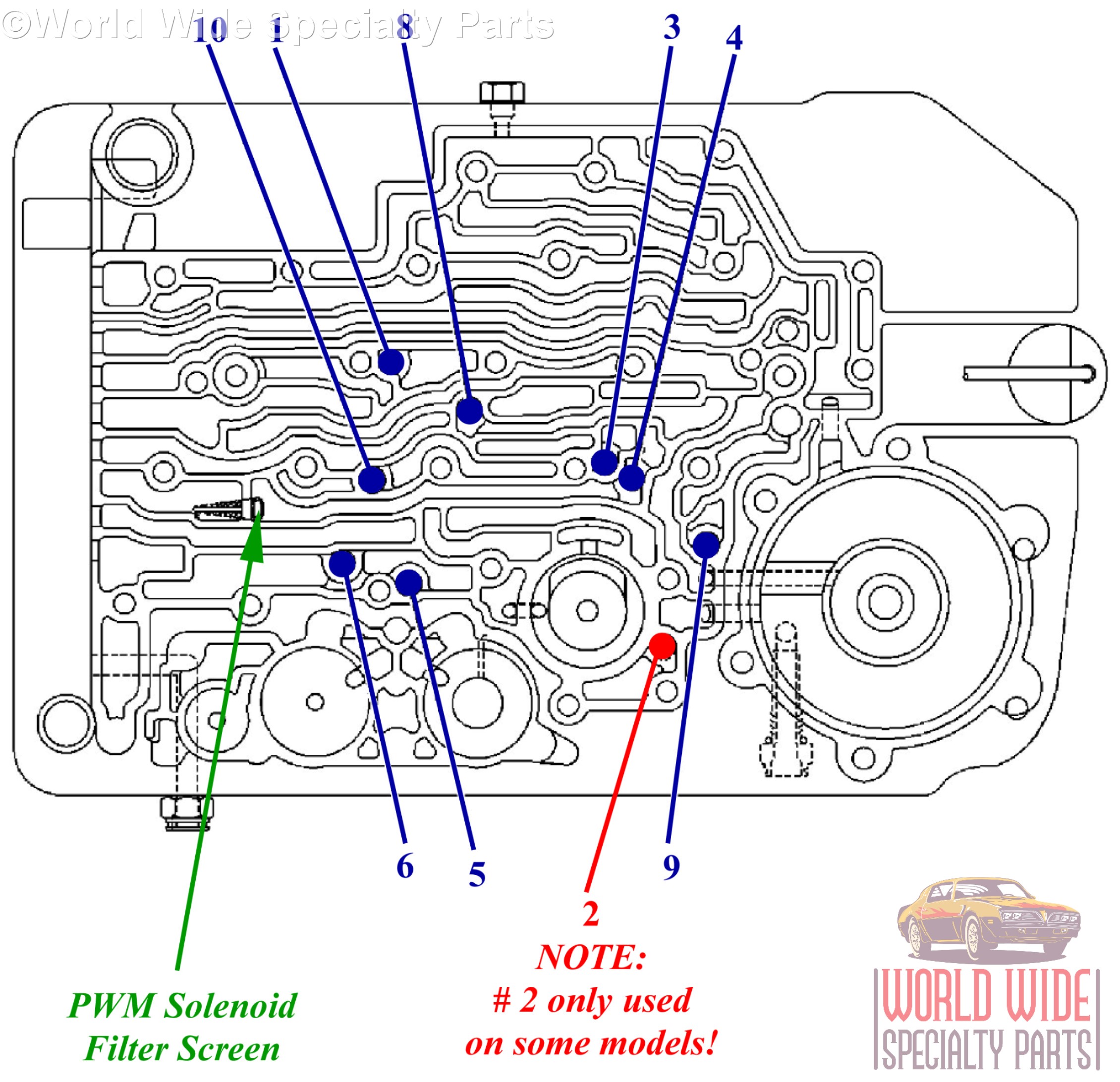
• Line Pressure Booster Kit***4L60E-LB2 • Checkballs (8) .250" • Boost Valve Spacer '96-'03 pump NOTES: The components included in this. Once all of the valve body retaining bolts have been installed, torque them to 100 in-lb, starting evenly from the center of the valve body working outwards (Figure 7). Figure 4 3-4

4l60e Valve Body Bolt Diagram
Low line pressure High line pressure 4L60 Oversized Throttle Valve 77968 Not compatible with early '82-'90 aluminum sleeve units. Helps cure: Low line rise 3-4 Clutch & band failure 4L60, 4L60-E, 4L65-E, 4L70-E, Powerglide, TH350C, TH400 Stator Support Bushing 35007A Bushing Style: Precision Material: Steel-backed copper alloy Width: 0.500"

4L60E Assembly
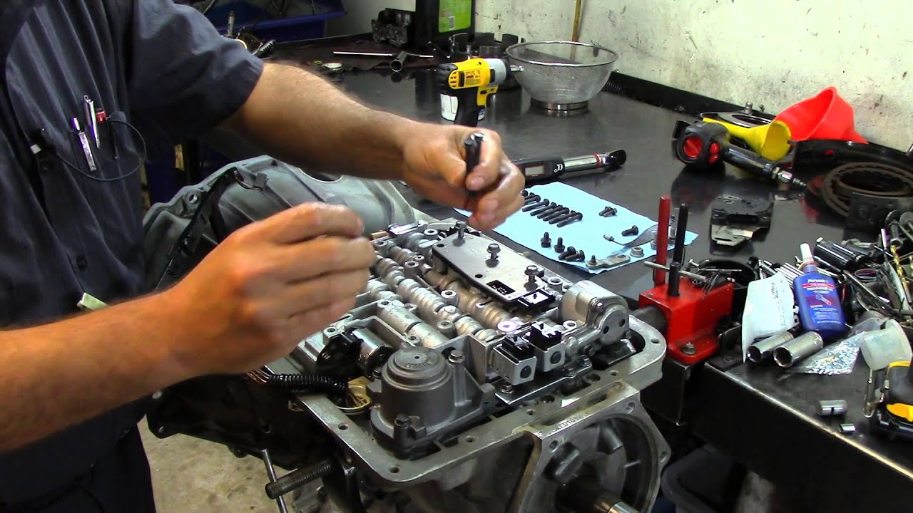
4L60E Transmission - Valve Body Installation Automatic Transmission 169K subscribers 364K views 10 years ago I have a complete rebuild of one o this units, but I think is a little vauge since I.
4l60e valve body check ball diagram Ball bearing in pan
The Street Smart Transmission Difference. If you want to solve all of your 4L60E valve body related issues, and have the security of a 3 Year/No Hassle Warranty, then you need to consider a remanufactured 4L60E valve body from Street Smart Transmission. Each one is built in a state of the art factory, by Certified valve body technicians.
4L60E Transmission Valve Body Installation Doovi
62 ill. DESCRiPTiON QTY. YEAR PART NO. REFERENCE NO. 74010 74010E Rear Wheel Drive TH700-R4 82-93 4l60E 93-Up 4l65E 01-Up
4l60e Valve Body Bolts Diagram CPT 4l60e
Tech Resources Transmission Valve Body Layout GM Print October 08, 2021 Email Share GM 4L60-E, 4L65-E, 4L70-E Valve Body Layout Sonnax valve body layouts provide a detailed overview of individual units making it quick and easy to determine what's available for the specific valve body you're working on. Each layout:

722.6 Valve Body Diagram
Automatic Transmission Valve Body Install - 4L60E Shift Kit - YouTube © 2023 Google LLC Click here to purchase the GM 4L60E DVD.

4l60e valve body parts diagram
This video shows the work of the 4L60E valve body
30+ 4l60e valve body bolt diagram DarinNeevah
The Sure Cure® Kit SC-4L60E '95-Later with PWM/EC3 control 77754-R2, 77754-TL, 77917-TL TCC/Lockup Symptoms. For worn isolator bore in unserviced valve body or for any factory-remanufactured valve body F-77754-TL4*, 77754-RM5, 77754-R2, 77754-SERV 3-4 Clutch failure, Code 894, 1870, Overheated converter, No 3rd, Delayed Reverse Stator.

4l60e wiring harness
Part Number: GM046 1995 4l60e Valve Body Identification Number of valve body solenoids: 5 EPC Solenoid: Early 3-2 Control Solenoid: PWM (metal, white) 10-15 Ω TCC Solenoid: PWM (metal, white) 10-15 Ω Manual Valve: Non-vented Casting: Bottom: open port over 3-2 valve, Bottom: no vent at manual valve Part Number: GM047
4l60e Valve Body Diagram CPT 4l60e
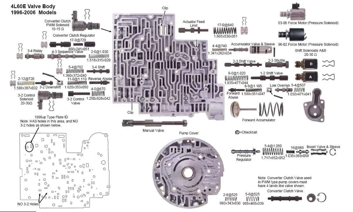
by Transmission Cooler Guide Previous Article Allison 1000 Transmission Guide & Information Next Article Allison 1000 Transmission Parts Diagram View all internal parts with this helpful 4l60e valve body diagram. Get more information about the 4l60e transmission valve body assembly

4l60e Accumulator Diagram
The 4L60e transmission is an electronically operated 4-speed transmission designed for vehicles with longitudinal engines. It utilizes four forward gears and one reverse gear and has a vehicle weight rating of 6000 lbs. Before adding the recommended 4L60e transmission fluid, this transmission weighs 146 lbs.

4l60e Transmission Valve Body Diagram Seeds Wiring
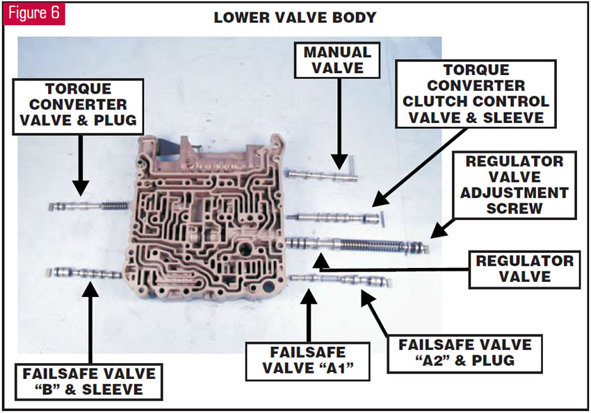
(Insert a labeled diagram of the 4l60e valve body) 1. Control Valve. The control valve is the main component of the valve body. Its role is to direct the flow of hydraulic fluid to the appropriate channels, which ultimately determines the gear shifts. It consists of various channels and passages that control the flow and pressure of the fluid.
4L60E Valve Body Parts Diagram Gm Transmission Parts Diagram Wiring
Wiring & Diagrams 4l60e Transmission Exploded View Diagram Related Posts 4l60e Valve Body Diagram 4l60e Valve Body Identification Guide 4l60e Mechanical Components Diagram Previous Article 4l60e Bellhousing Bolt Pattern Diagram Next Article What Causes A 4l60e Transmission To Slip
30+ 4l60e valve body bolt diagram DarinNeevah
April 12, 2017 Email Share GM 4L60-E Valve Body Identification Guide Was this tech helpful? What do these mean? 4L70-E Transmission 4L60-E Transmission 4L65-E Transmission